

Our AIRFLOW dilution and flue boost fans are manufactured in the United Kingdom and distributed throughout Australia by PWS Hunt Boilers
The range is available in standard form (GBDF series) typically used with atmospheric boilers and water heaters of around 75% efficiency.
In addition, an enhanced corrosion resistant version is available (SSDF series) incorporating stainless steel fan cases. These are ideally suited for installation into stainless steel ducting, higher efficiency boilers, or any boiler likely to produce condensation as part of its normal operation.
The key features of the product range include:
Flexibility to install into new or existing plant rooms
Eliminates the need for more expensive larger diameter or external flues
Provides an alternative to the refurbishment of current flue installations
Efficient and quiet operation capable of overcoming system resistance in flue ducts
Inbuilt vane switch with position proving capability, that causes boiler shut down in the event of a fan failure
High levels of protection with the use of stainless steel on the SSDF series, and Aluzinc coated steel on GBDF series.
Fresh air added into the boiler's discharge flue duct which dilutes the flue gases, making them more suitable for disbursement at low levels
CHOOSING THE CORRECT DILUTION FAN
The fan selection depends on the airflow required to dilute the combustion products to a safe level and/or the pressure loss in the ductwork system that the fan has to overcome.
Note: The dilution calculations offered are based on reducing the CO2 content to 1% and should be used in conjunction with all requirements contained within AS/NZS 5601.1 for Gas Installations.
To select the appropriate fan for your application follow these easy steps.
Step 1: Determine the Flow Rate required
The required volume flow rate of diluted flue gases necessary for a given boiler can be calculated as follows:
Flow Rate in Litres per Second (L/s) = 3.6 x rated input of boiler in kW
Step 2: Determine the Flue Pressure Resistance
Part 1 - Straight Section
First, you must determine the flue pressure resistance in all the straight sections of the ductwork.
Add up the total length of straight sections of ductwork. Multiply this total length by the pressure loss per metre of duct which you can determine from the following table.
(Note: If you have square duct instead of round, use the column for the next smaller round duct as an approximation, i.e. For 350 square duct you would use the figure for 300 round duct.)
PART 2 - BENDS
Second, you must determine the flue pressure resistance in all the bends.
Loss Coefficient KL = (number of bends x 1.2) + 5.0
(Note: This formula already incorporates an allowance for a low restriction grille in the entry and the exit. If you have other restrictions in the ductwork (e.g. hats over the ends of the ducts, then you need to allow for these separately)
Pressure Loss (bends) = 760 x Flow Rate (L/s) x Loss Coefficient (KL) / Flue Dia. (mm) Squared
Therefore Total Flue Pressure Resistance = result from part 1 + result from part 2
Once you have determined the Flow Rate Required and Flue Pressure Resistance, use the following table to select the appropriate fan model.
FLUE PRESSURE RESISTANCE FOR STRAIGHT SECTIONS (PASCALS PER METRE)

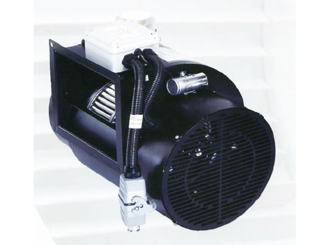
Model SSDF2 in standard trim, suitable for Natural Gas non-condensing boilers
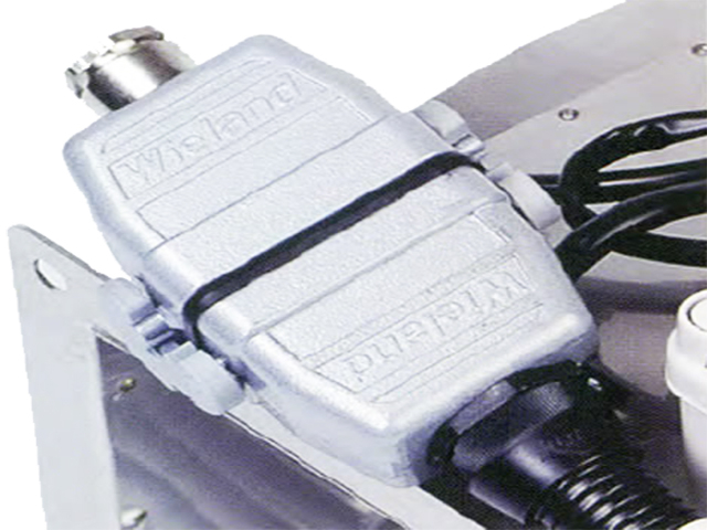
All AIRLOW dilution fans are supplied with pressure proving safety interlocks
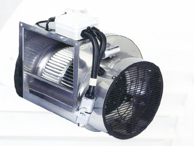
Model SSDF2 in Stainless Steel trim, suitable for Natural Gas condensing boilers